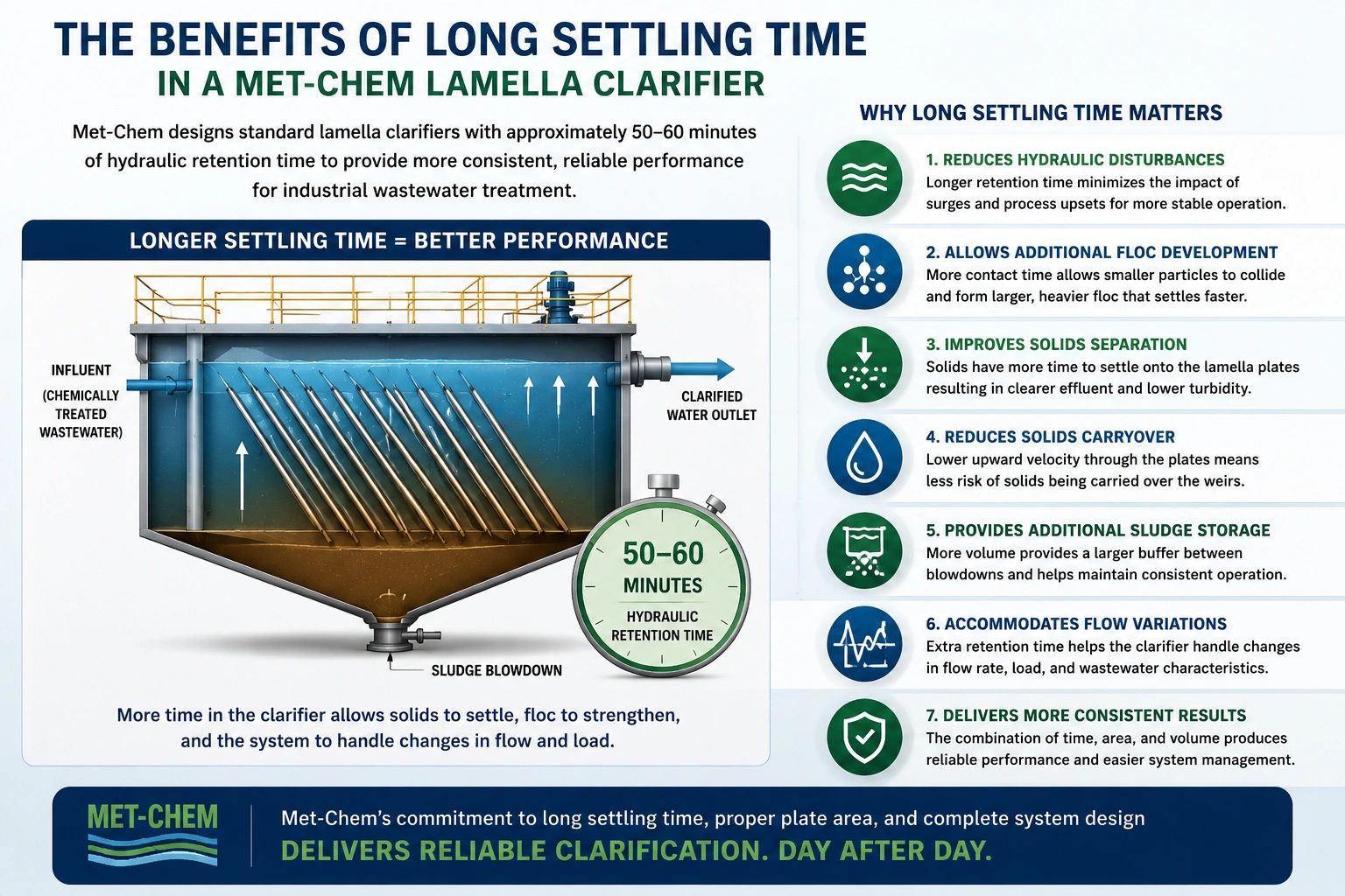
Proper clarifier sizing requires more than selecting a tank based on gallons per minute. Met-Chem evaluates wastewater flow, projected settling area, solids settling characteristics, plate configuration, retention time, chemical treatment, sludge production, and hydraulic conditions when designing an industrial clarifier.
An industrial clarifier must provide enough settling capacity for suspended solids to separate from the upward-flowing wastewater.
For inclined plate and lamella clarifiers, the settling area is greatly increased by installing multiple parallel plates inside the tank.
However, theoretical plate area is only one part of the design.
A successful industrial clarifier must also provide:
Met-Chem designs the complete clarification process rather than sizing a clarifier from flow rate alone.

The first step is understanding the wastewater.
Met-Chem typically evaluates:
Two facilities operating at the same flow rate can require significantly different clarifiers.
A 100 GPM wastewater stream containing large, dense mineral solids behaves very differently from a 100 GPM wastewater stream containing light metal-hydroxide floc.
Flow starts the sizing process. The characteristics of the wastewater complete it.
Wastewater flow is generally expressed in gallons per minute:
Q = Flow Rate in GPM
Average flow is useful for understanding normal operation.
Peak flow is equally important.
A clarifier that performs well at average flow may experience solids carryover when flow temporarily increases.
Clarifier design should therefore consider both:
Average Design Flow
and
Peak Design Flow
EPA design guidance has long treated surface overflow rate and peak hydraulic loading as important clarifier sizing criteria because excessive upward flow can carry solids into the effluent.
For industrial systems, Met-Chem also considers whether the upstream treatment process provides equalization.
An equalization tank can reduce sudden hydraulic changes and allow wastewater to enter the treatment system at a more consistent rate.
One of the fundamental clarifier sizing relationships is the surface overflow rate, sometimes called surface loading rate or hydraulic loading rate.
The basic relationship is:
Surface Overflow Rate = Flow ÷ Settling Area
or:
SOR = Q ÷ A
Where:
Q = wastewater flow
A = effective settling area
This relationship represents the upward hydraulic velocity imposed on the clarification area.
If water moves upward faster than the solids can settle downward, solids may be carried out with the clarifier effluent.
EPA guidance describes surface overflow rate as an important measure of clarifier hydraulic capacity.
For an inclined plate clarifier, the effective settling area is based on the horizontal projected area of the plates, not simply the footprint of the tank.
Inclined plates dramatically increase the amount of settling area that can be installed inside a compact clarifier.
The projected area of one inclined plate can be calculated as:
Projected Area = Plate Length × Plate Width × cos(θ)
Where:
θ = plate angle from horizontal
For multiple plates:
Total Projected Settling Area = Number of Plates × Plate Length × Plate Width × cos(θ)
Met-Chem commonly uses plates installed at approximately 60 degrees from horizontal.
At 60 degrees:
cos(60°) = 0.50
That means the horizontal projected area of a plate is approximately half of its actual physical area.
Assume an inclined settling plate is:
4 feet wide
and
8 feet long
Physical plate area:
4 ft × 8 ft = 32 ft²
At a 60-degree angle:
Projected Area = 32 × cos(60°)
Projected Area = 32 × 0.50
Projected Area = 16 ft²
If the clarifier contains 40 comparable settling plates:
40 × 16 ft² = 640 ft² projected settling area
This illustrates why inclined plate clarifiers can provide substantial settling area within a relatively small tank.
Once a design surface loading rate has been selected, required settling area can be estimated using:
Required Area = Flow ÷ Design Surface Loading Rate
or:
A = Q ÷ SLR
For example:
Assume:
Flow = 100 GPM
Design loading = 0.25 GPM/ft²
Then:
A = 100 ÷ 0.25
A = 400 ft² of projected settling area
This does not automatically mean that every 100 GPM industrial wastewater application should use 400 ft².
The appropriate loading rate depends on the type of solids, settling characteristics, chemical treatment, required effluent quality, and other process conditions.
Published industrial inclined-plate guidance commonly shows that lighter metal-hydroxide solids require more conservative loading than dense, rapidly settling particles.
Clarifier performance ultimately depends on the relationship between:
Upward water velocity
and
Downward solids settling velocity
For effective separation:
Solids settling velocity should exceed the upward hydraulic velocity through the clarification area.
If solids settle more slowly than the water rises, they can be carried upward and discharged with the clarified water.
This is why wastewater testing is valuable.
A simple settling test can provide information about:
Where wastewater characteristics are unusual, laboratory or pilot testing can provide more reliable design information than using a generic loading value. EPA design guidance also recommends testing or special consideration where industrial wastewater characteristics differ significantly from typical wastewater.
Met-Chem commonly uses inclined settling plates positioned at approximately 60 degrees.
Plate angle affects both:
Projected settling area
and
the ability of accumulated sludge to slide down the plate.
A flatter plate provides more projected area.
However, if the plate becomes too shallow, sludge may not slide effectively.
For industrial wastewater, the plate angle must therefore balance hydraulic performance with reliable solids removal.
EPA literature on inclined plate settlers notes typical plate angles around 55–65 degrees, depending on the application.
Projected settling area determines hydraulic settling capacity.
Tank volume determines hydraulic retention time.
Met-Chem considers both.
Hydraulic retention time can be estimated as:
Retention Time = Available Liquid Volume ÷ Flow Rate
For example:
If a clarifier contains approximately:
6,000 gallons
and receives:
100 GPM
then:
Retention Time = 6,000 ÷ 100
Retention Time = 60 minutes
Met-Chem standard industrial clarification systems are commonly designed around approximately 50–60 minutes of overall hydraulic retention time, depending on the configuration.
Retention time can provide:
For industrial wastewater, this can be particularly valuable because flow and chemistry are rarely perfectly constant throughout a production day.
Plate spacing is another important design consideration.
Reducing the distance between plates allows more plates to fit within a given tank.
More plates can theoretically provide additional settling area.
However, tighter plate spacing can also reduce the available channel width for:
Industrial wastewater often produces relatively bulky floc.
Examples include:
The plate spacing must be large enough to prevent the plate pack from becoming excessively restricted or blinded by solids.
Published inclined-plate guidance shows that plate spacing can vary significantly based on solids characteristics and concentration.
More plates are not automatically better.
It is possible to design a very small tank with a large amount of theoretical plate area.
That may produce an attractive GPM rating on paper.
However, industrial wastewater clarification requires more than theoretical area.
A clarifier also needs enough physical volume to accommodate:
Met-Chem therefore evaluates projected settling area and tank retention time together.
A large plate pack inside an undersized tank is not necessarily a well-designed industrial clarifier.
Consider two clarifiers that are both advertised for:
100 GPM
Provides sufficient inclined plate area but has very little tank volume.
At 100 GPM, the hydraulic retention time may only be 20–25 minutes.
Provides comparable projected plate area but has significantly more liquid volume.
At 100 GPM, the retention time may be approximately 50–60 minutes.
Both units may theoretically have enough plate area for the flow.
However, Clarifier B provides substantially more hydraulic buffering and process volume.
For industrial wastewater where solids concentration, chemical treatment, and flow can vary, Met-Chem prefers a conservative approach that considers the entire treatment process.

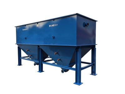
Met-Chem manufactures standard industrial clarifiers in common capacities including:
Larger and custom systems are also available.
These ratings provide a starting point.
Final sizing should be based on the actual wastewater application.
Clarifiers should not be evaluated using average GPM alone.
Assume a system normally operates at:
80 GPM
but periodically experiences:
120 GPM
The clarifier may perform very differently during the peak-flow condition.
The higher flow increases upward hydraulic velocity through the settling plates.
If the hydraulic velocity approaches or exceeds the settling velocity of the floc, solids carryover can occur.
This is one reason Met-Chem often recommends equalization ahead of industrial wastewater treatment systems.
A properly sized equalization tank can allow variable production wastewater to enter the treatment process at a more consistent rate.
Flow is not the only load entering a clarifier.
Solids also matter.
A wastewater stream with:
100 mg/L suspended solids
places a much different solids load on a clarifier than wastewater containing:
5,000 mg/L suspended solids.
Higher solids loading can affect:
A well-designed clarification system should therefore consider both:
Hydraulic Loading
and
Solids Loading
Industrial clarifiers frequently treat wastewater containing dissolved metals.
The clarifier does not directly settle dissolved ions.
Chemical treatment first converts these dissolved contaminants into suspended particles.
For example:
Dissolved Metal → pH Adjustment → Metal Hydroxide Precipitate
The resulting solids are then coagulated and flocculated before clarification.
Chemical treatment can greatly increase the amount of solids entering the clarifier.
That solids production should be considered when determining:
Clarification efficiency depends heavily on the quality of the floc entering the plate section.
A very fine precipitate may settle slowly.
Proper coagulation and polymer addition can combine these particles into larger floc.
A clarifier system may therefore include a dedicated flocculation compartment.
Flocculation should provide:
Excessive mixing can break floc apart.
Insufficient mixing may prevent good floc formation.
The clarifier and flocculation system should therefore be designed together.
Every pound of solids removed by the clarifier eventually reaches the bottom sludge section.
The sludge cone must therefore provide adequate capacity between blowdown cycles.
Important considerations include:
However, Met-Chem does not recommend using the sludge cone as long-term solids storage.
Frequent removal is generally preferred.
Frequent sludge removal helps maintain available sludge volume and reduces the risk of solids accumulating near the plate packs.
A common operating strategy is to remove smaller quantities of sludge automatically at regular intervals.
The proper timing is determined during system startup based on actual solids production.
Automatic blowdown can help maintain more stable clarifier conditions.
Clarifier sizing and filter press sizing are related.
The clarifier determines how much solids-bearing sludge is generated.
The filter press determines how quickly that sludge can be dewatered.
A complete Met-Chem wastewater treatment design may evaluate:
Wastewater Flow → Pounds of Solids → Clarifier Sludge Volume → Filter Press Capacity
The clarifier is generally continuous.
The filter press is generally batch-operated.
A sludge holding tank between the two systems provides operating flexibility.
A simplified Met-Chem sizing process might look like this:
Example:
120 GPM average flow
Example:
150 GPM temporary peak
Identify dissolved metals, suspended solids, pH, and other contaminants.
Establish precipitation, coagulant, and polymer requirements.
Evaluate floc size and settling behavior through laboratory testing when appropriate.
Use the selected design loading criteria and wastewater flow.
Determine plate size, angle, spacing, and number of plates.
Ensure adequate process volume rather than relying only on plate area.
Determine anticipated solids generation and blowdown requirements.
Evaluate sludge pumps, storage, and filter press capacity.
This complete approach provides a more reliable industrial wastewater system than simply matching a clarifier to the plant's maximum GPM.
Selecting the Clarifier Only by GPM
Two 100 GPM wastewater streams may behave completely differently.
Projected area is important, but it does not replace adequate tank volume and hydraulic design.
Short periods of excessive flow can cause solids carryover even if average flow is acceptable.
Chemical precipitation and flocculation directly affect what the clarifier must separate.
The sludge generated by the treatment process must be removed, stored, and dewatered.
High theoretical plate area is not helpful if the plate channels repeatedly clog.
Sludge accumulation reduces available clarifier capacity and can eventually affect plate performance.
Industrial clarifier sizing considers wastewater flow, projected settling area, surface loading rate, settling characteristics, solids loading, plate configuration, hydraulic retention time, sludge production, and chemical treatment.
Surface overflow rate is the wastewater flow divided by effective settling area.
SOR = Q ÷ A
It represents the hydraulic loading applied to the clarifier settling area.
For an inclined plate:
Projected Area = Length × Width × cos(plate angle)
Total projected area is the projected area of one plate multiplied by the number of effective settling plates.
Plate angle affects both projected settling area and the ability of collected solids to slide downward.
Met-Chem commonly uses plates installed at approximately 60 degrees from horizontal.
No. Plate spacing, hydraulic distribution, tank volume, solids movement, and wastewater characteristics also matter.
The appropriate retention time depends on the application. Met-Chem standard industrial clarification systems commonly provide approximately 50–60 minutes, depending on configuration.
Both should be evaluated. Peak hydraulic flow can cause solids carryover even when average flow is acceptable.
Wastewater testing can provide valuable information about precipitation, flocculation, settling behavior, and sludge generation. Met-Chem can use wastewater analysis and testing data as part of the sizing process.
Met-Chem designs and manufactures industrial clarifiers, lamella clarifiers, inclined plate clarifiers, replacement plate packs, filter presses, and complete industrial wastewater treatment systems.
For clarifier sizing, provide as much information as possible:
Met-Chem can evaluate the wastewater treatment process and recommend an appropriate clarifier size and configuration.
Contact Met-Chem for industrial clarifier design, lamella clarifier sizing, equipment selection, or a complete wastewater treatment system.

We use cookies to analyze website traffic and optimize your website experience. By accepting our use of cookies, your data will be aggregated with all other user data.